From idea to assembled board.
Describe the product you need. Our design platform turns it into a parts list, a schematic and a routed board, built to industry standards such as IPC-2221 and IPC-7351. Every stage passes automated electrical and design-rule checks before the next one starts. Then we source the parts and build it.
Five stages. Fifteen checks. No shortcuts.
Each step in the studio has to pass before the next one opens. Change something early and every later step is rebuilt, so a design never ships with stale results.
Requirements
You describe the circuit and the board. The platform asks what it needs to know.
1.1Idea & board1.2Design brief & BOM1.3Standards check
Components
Every part is matched to a verified symbol and footprint, then rated for its role.
2.1Library match2.2Ratings check2.3Sourcing & BOM freeze
Schematic
Every pin is connected against verified pin data and drawn as a wired schematic.
3.1Netlist3.2Schematic3.3Electrical rules check
Layout
Placement, autorouting and ground pours, checked against fabrication rules.
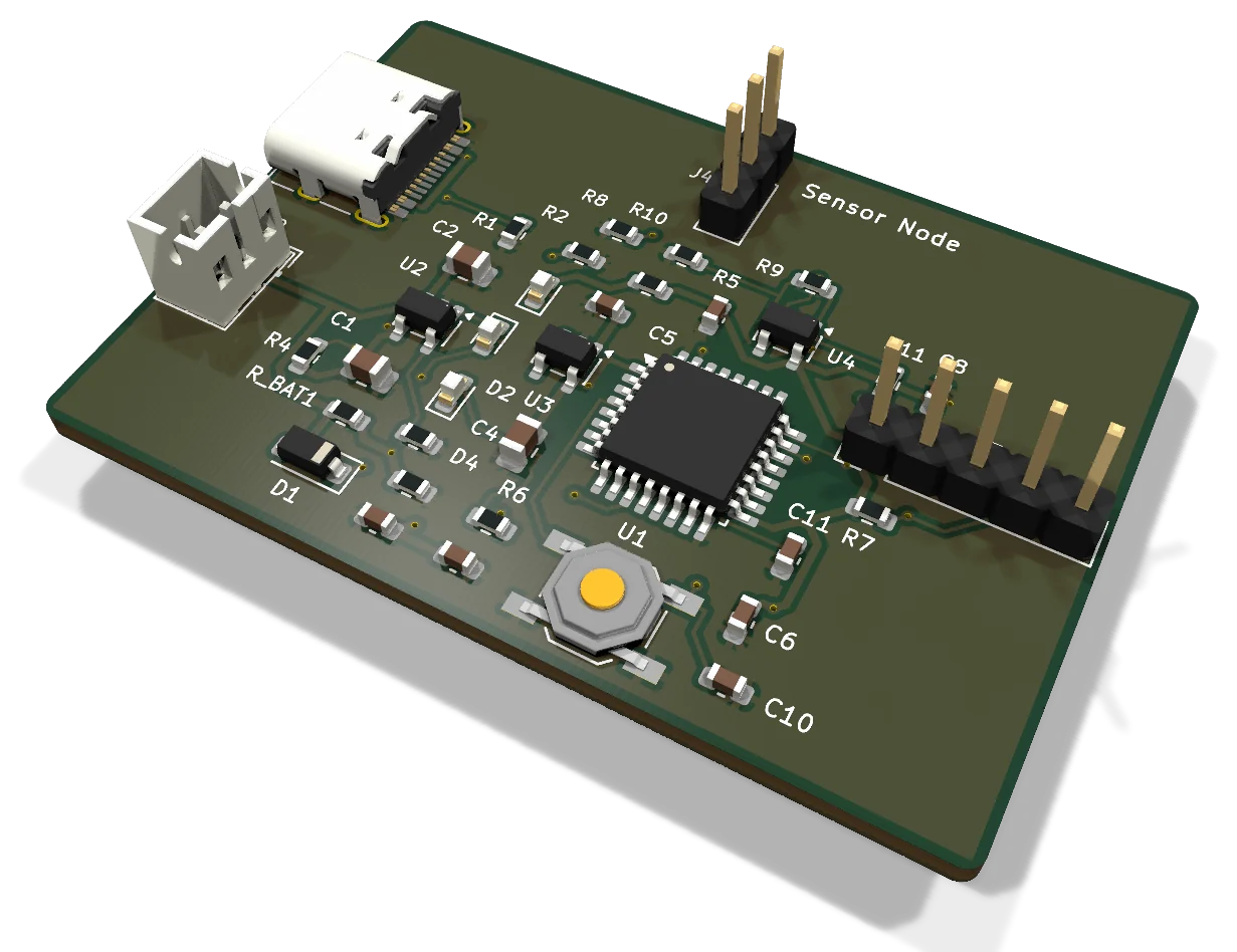
4.1Placement4.2Routing4.3Design rules check & 3D
Production
Manufacturing files, a safety review and a frozen release.
5.1Manufacturing files5.2Safety review5.3Release
Real engineering standards. Modern tools.
Speed is only useful when the board is right. Every design follows the electronics standards manufacturers work to, and every result is checked by rules, not by trust.
Built to industry standards
- IPC-2221 conductor spacing, with wider clearances for mains voltages
- IPC-7351 land patterns from a verified component library
- Electrical and design rules checks on every schematic and every board
- Voltage, current, power and thermal ratings checked for every part
- RoHS and REACH requirements considered when parts are sourced
Designed with modern tools
- AI and language models turn your description into requirements, a parts list and connections
- Machine learning matches each part to the right component and package
- Engineering algorithms place parts, route copper and pour ground planes
- Rule engines verify every step before the next one can start
- Engineers review what automation cannot judge, and sign off mains designs
One partner from schematic to shipped board.
Use the studio on your own, bring in our engineers, or hand over the whole build. The files stay yours at every step.
PCB design
Automated design to industry standards, reviewed by our engineers. You receive the full, editable design project, not a locked file.
Design services 02Component sourcing
Purchasing part numbers fixed at BOM freeze, checked for ratings and lifecycle, bought from authorized distributors.
Sourcing 03Fabrication & assembly
Gerbers, BOM and pick-and-place go to board fabrication and SMT assembly, with delivery into the EU from Tallinn.
ManufacturingIndicative lead time, in seconds.
Pick your board, sourcing and volume. Send the result to us as a quote request when it looks right.
- Inspection
- AOI + X-ray + E-test
- Sourcing
- Authorized distributors
- Next step
- Design review, then pilot
Indicative only. The quote confirms lead time after we review your files and current stock.
Have a board in mind?
Describe it in the studio, or send us your BOM and files. An engineer in Tallinn reviews every quote request.